
Skip to content

10 Best Cemented Carbide Inserts for CNC Machining

Choosing the right insert can decide whether a CNC job runs smoothly or leaves a rough edge and a worn tool. This guide to the 10 Best Cemented Carbide Inserts for CNC Machining compares options by grade, coating, geometry, and intended workpiece material. The aim is practical: help machinists narrow their choices, not promise one insert will suit every setup.

Cemented-carbide researcher H. O. Andrén’s work offers a useful reminder: “Microstructure shapes performance.” This is a paraphrase, not a verified verbatim quotation. Carbide composition and binder content affect hardness, toughness, and wear behavior. In the shop, those differences show up in familiar ways: a chipped corner, a shiny flank, or a finish that drifts after repeated passes. Small details matter.

The selections consider turning, milling, and general-purpose applications, alongside factors such as heat, interrupted cuts, and chip control. A coating that performs well in steel may not be the best choice for aluminum or stainless steel. Machine rigidity and coolant also change the result. No ranking can replace a controlled trial on the actual machine. That caveat matters. Use the list as a starting point, then check the insert maker’s cutting data and test cautiously. The best choice is often the one that stays predictable in your conditions—not the one with the boldest catalog claim.
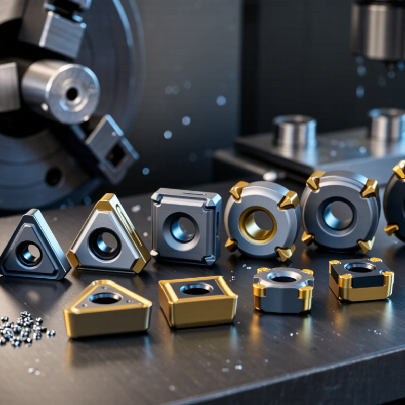
10 Best Cemented Carbide Inserts for CNC Machining

What Cemented Carbide Inserts Are and How They Work

Cemented carbide inserts are replaceable cutting tips used in CNC turning, milling, and drilling. They are usually made from hard tungsten carbide particles held together by a metal binder. The carbide resists abrasion, while the binder helps the insert withstand cutting forces. Neither quality makes an insert indestructible.

As the spindle turns, the cutting edge shears material from the workpiece. The insert’s shape directs chips away and influences heat, surface finish, and cutting pressure. A chipbreaker groove can curl long chips into shorter pieces. The holder keeps the insert seated at a precise angle. No insert is universally best. Interrupted cuts can chip an edge that performs well on a steady pass.

Tips: Match the insert grade and geometry to the workpiece and operation. Check the manufacturer’s cutting-speed and feed recommendations, then adjust cautiously. Watch for chatter, built-up material, and uneven edge wear. Chip color can offer clues, but it is not a reliable diagnosis by itself. Change one setting at a time; otherwise, the cause of a better or worse result may stay unclear.

How Insert Grades, Shapes, and Coatings Affect Performance

Insert performance starts with the workpiece, not the catalog. ISO 513 assigns application groups: P for steel, M for stainless steel, K for cast iron, and N for non-ferrous metals. S and H address heat-resistant alloys and hardened materials. Treat these groups as a starting point, not a guaranteed grade choice. Interrupted cuts, coolant, and machine rigidity can change the result.

Coated grades often suit sustained production, while uncoated, sharp-edged grades can help with soft, gummy alloys. That trade-off matters. PVD coatings can preserve a sharper edge; CVD coatings can provide a thicker thermal barrier, though performance depends on the substrate and process. Geometry matters, too. Round inserts or large nose radii strengthen the edge, but may raise cutting forces and chatter risk. Positive-rake geometries cut freely in thin sections; tougher negative geometries tolerate heavier loads.

The U.S. Geological Survey’s 2024 Mineral Commodity Summaries estimated world tungsten mine output at 78,000 metric tons in 2023. That figure tracks raw-material supply, not insert life, and cannot identify the best coating. Test candidates at the same speed and feed, then compare flank wear, chip shape, and surface finish. One caveat: a stable test cut may still fail on the next material batch.

10 Best Cemented Carbide Inserts for CNC Machining - How Insert Grades, Shapes, and Coatings Affect Performance

Selection guide: These are common insert configurations, not brand-specific products. Grade designations and performance vary by manufacturer; match the insert to the work material, operation, machine rigidity, and cutting conditions.

No. Insert shape / example designation Typical grade or substrate focus Common coating options Best-suited materials and operations Performance strengths Main trade-off
1 CNMG
80° diamond, negative-rake style
Tough carbide grades for general steel turning; commonly selected from steel-focused grade families CVD TiCN/Al₂O₃/TiN; PVD coatings may suit sharper-edge applications Steel roughing and general turning; suitable for stable setups and heavier cuts Strong cutting edge and multiple usable corners; versatile for common external turning Negative geometry needs adequate machine power and workpiece rigidity
2 DNMG
55° diamond, negative-rake style
Steel or stainless grades selected for the specific material and cut; tougher grades for interrupted cuts CVD multilayer coatings for many steel applications; PVD options for sharper edges or stainless steel Profile turning and shoulder work where a more pointed tool shape is useful Good access to contours and features compared with a 80° insert The narrower point is less robust than a larger included-angle shape
3 VNMG
35° diamond, negative-rake style
Fine-grain, wear-resistant grades for finishing; tougher grades may be preferable for interrupted cuts PVD TiAlN, AlTiN, or TiCN options, depending on work material and cutting conditions Fine profiling and finish turning of steel and other suitable materials Excellent access to narrow profiles and tight contours Very sharp point is vulnerable to chipping; needs a stable setup
4 SNMG
Square, negative-rake style
Tough grades for roughing; wear-resistant grades for stable continuous cuts CVD Al₂O₃-based coatings for heat and wear resistance; PVD alternatives for edge toughness Heavy turning, facing, and machining with a rigid toolholder and workpiece Strong corners and a robust cutting edge for demanding cuts Requires clearance planning and more cutting force than many positive inserts
5 TNMG
Triangle, negative-rake style
General-purpose steel or cast-iron grades, selected for the workpiece and operation CVD multilayer coatings for many production cuts; PVD coatings for sharper edges General turning and facing where a compact insert and several corners are useful Useful balance of economy, access, and cutting-edge strength Less robust than a square or round insert under heavy cutting loads
6 WNMG
Trigon, negative-rake style
Tough or wear-resistant grade families for steel and cast iron, according to cutting conditions CVD coatings commonly used for wear resistance in production turning General and rough turning; design can provide multiple cutting corners, depending on insert specification Good edge economy and a robust profile for many turning jobs Not every corner or holder setup is suitable for all profiling operations
7 CCMT
80° diamond, positive-rake style
Fine-grain grades for finishing and lower cutting forces; choose a material-specific grade PVD TiAlN, AlTiN, or TiCN coatings; uncoated options may be used for some nonferrous work Light turning and boring, especially on smaller or less-rigid machines Positive cutting geometry can reduce cutting forces and promote a clean cut Less edge support than a comparable negative insert
8 DCMT
55° diamond, positive-rake style
Sharp, fine-grain grades for finishing and contouring; grade should match the work material PVD coatings are common where edge sharpness and resistance to built-up edge are priorities Light profiling, boring, and finish turning of steel or stainless steel Good contour access with relatively low cutting forces Pointed tip can be more prone to damage in rough or interrupted cuts
9 CCGT / CCGT-style polished insert
80° diamond, sharp positive edge
Fine-grain, sharp-edge carbide, often uncoated or polished for nonferrous machining Often uncoated and polished; coating choice depends on the material and edge requirements Finishing aluminum and other nonferrous materials; use appropriate geometry and chip control Sharp edge and smooth rake face can help reduce built-up edge and improve finish Not the best choice for heavy cuts or abrasive materials without a suitable grade
10 Round insert
R-shaped milling or turning insert
Tough grades for milling and interrupted cuts; material-specific grades remain essential CVD or PVD coatings selected for the work material and cutting temperature Face or shoulder milling and suitable turning operations; useful where a strong rounded edge is needed Strong edge and gradual engagement can support productive milling when properly programmed Cutting forces and effective cutting angle vary with depth of cut and tool engagement

General guidance: ISO application groups commonly include P for steel, M for stainless steel, K for cast iron, N for nonferrous metals, S for heat-resistant alloys, and H for hardened materials. Coating type alone does not determine performance: substrate toughness, edge preparation, chipbreaker geometry, cutting speed, feed, depth of cut, coolant, and setup rigidity all matter.

Ten Cemented Carbide Inserts for Common CNC Machining Tasks

For aluminum turning, a sharp, polished carbide insert can limit built-up edge and leave a cleaner surface. Steel turning often favors a tougher, negative-rake insert with a chipbreaker suited to the feed and cutting depth. Roughing inserts need reinforced edges and larger corner radii, though excessive pressure can still cause chatter. For stainless steel, a tough grade and open chipbreaker may help manage heat and work hardening. Cast iron commonly calls for a wear-resistant grade and a stable edge because abrasive particles can shorten tool life. Check the actual workpiece, not just its label.

For broad flat surfaces, a face-milling insert balances edge strength with finish requirements. A shoulder-milling insert helps produce square walls, but tool runout can leave visible steps. Indexable-drill inserts suit repeated holes when the machine and holder provide enough rigidity. Threading inserts need the correct profile and pitch; a small mismatch can spoil the thread quickly. Grooving inserts benefit from a narrow, stable cutting edge and reliable chip evacuation. Fit matters. I would not treat these choices as fixed recipes: grade, geometry, coolant, and setup all change the result. Even a good insert may fail in a flexible workholding setup.

How to Match an Insert to Materials and Cutting Conditions

Matching a cemented carbide insert starts with the workpiece, not the catalog description. Steel, stainless steel, cast iron, and aluminum produce different chips and heat. For tough stainless steel, a sharper, positive-rake geometry can reduce cutting forces and help prevent work hardening. Cast iron often suits a stronger edge that tolerates abrasive chips. Aluminum needs a keen edge and generous chip space to limit built-up material.

Then consider how the cut behaves. A continuous finishing pass can use a sharper edge and a smaller nose radius for a finer surface. Interrupted cuts, scale, or a rigid setup with vibration may call for a tougher grade and a sturdier edge preparation. Heat changes everything. Coatings can help with wear and heat, but the right choice depends on speed, coolant, and the specific alloy. A useful starting point—not a verdict.

In shop practice, chip shape is a quick clue. Long, tangled chips may point to a chipbreaker mismatch, while uneven flank wear can suggest excess speed or poor setup rigidity. Check the insert after a short test cut, and change one setting at a time. I still find this easy to misjudge: a grade that survives roughing may wear too quickly during finishing. Record the material, cutting speed, feed, depth, and observed wear. Small notes make the next selection less of a guess.

10 Best Cemented Carbide Inserts for CNC Machining

Typical starting cutting-speed ranges for coated carbide inserts in turning

These broad ranges are starting points in meters per minute (m/min), not guaranteed settings. The best insert grade and cutting speed depend on the specific alloy, insert geometry and coating, workpiece hardness, and machine rigidity. Check the insert supplier’s recommendations and adjust based on cutting conditions.

How to Install, Use, and Maintain Inserts Safely

Before installing a cemented carbide insert, stop the spindle and follow the machine’s lockout procedure. Let it cool. Wear safety glasses and cut-resistant gloves when handling sharp edges. Brush chips from the pocket; trapped debris can tilt the insert and cause uneven cutting. Check the seat for dents, burrs, or cracks, then fit an insert with the correct shape and orientation. Use the specified screw and torque value. Never guess torque. Over-tightening can damage the insert or holder, while a loose screw can let the insert shift.

During machining, keep hands away from the cutting zone and use the machine guard. Watch the chips, surface finish, and cutting sound. A sudden change may signal wear, poor clamping, or unsuitable cutting conditions. Stop the machine before inspecting anything. Do not touch a hot insert. Small details matter. In a busy shop, it is easy to blame the tool before checking the setup; that can waste good inserts.

After use, remove chips with a brush and inspect each cutting edge under good light. Rotate an insert only if its design provides another usable edge, and secure it again to the specified torque. Replace inserts with cracks, deep chips, or uncertain damage. Keep them dry and protected in their original storage compartments. A simple record of tool life and cutting conditions helps reveal patterns, though shop results can vary with material and setup.